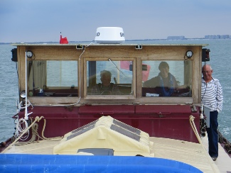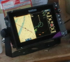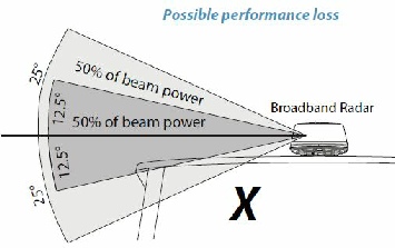
We mounted the radar dome directly to the middle section of wheelhouse roof, the manual stated that this could cause some performance loss, as the wide vertical beam width would mean that some of the transmitted signal would hit the flat roof. We hoped that the roof being plastic would make this OK, but the picture of the display during the crossing, below left shows that we had some interference on the port side abaft the beam. It can be seen as a trail of false returns spreading out from the centre of the radar display and going left and down.
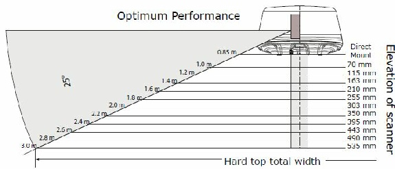
The roof could be the cause so we have designed a small platform to raise the dome by 21cm, any increase in height will give more range as well. It will be made from glued together 24mm thick Vekaplan (plastic), from when we made the roof. The design is shown below and the height calculation table from the manual is also shown. The bolt holes will match those for the dome so there won’t be extra holes in the roof. Done in 2018.


Vekaplan comes with its own bonding glue which effectively makes a weld between the pieces. Cosmetically the dome did look a bit squat when mounted directly on the roof, so the raised position should look a little better.
The calculated horizon for our radar height of 3.6m was only 4.2 NM and raising the height by 21cm to 3.8m only gives a horizon increase to 4.35 NM. However, if a target ship’s height is 20m then we should detect it at 14 NM which would seem to be a reasonable range to be thinking of other vessels.
To carry out proper collision avoidance on the radar, it would need an accurate heading input at a high data rate, our fluxgate compass wasn’t up to that so we did without. We used the CPA calculations from the AIS on the chart plotter and the VRB marker on the radar to assess passing ships.